PS3s were brand-new tech when I wrote those, but now they're a generation or two (or maybe three) old, and you might have landed here wondering what you can do with the junk you have that used to be a really cool gaming system.
I should have a central place for the technical specifications of the PS3 laser part itself, and the arrangement that worked for us, in a concise text.
Here I'll collate from the four build posts;
- Diode Pinout
- Working power settings
- Brief description of diode component extracting, installing, handling
- (!!) Full power supply circuits will not be provided here. Sam's Laser FAQ is my usual recommendation for anything laser-related. Better yet, design your own. Make friends with someone smarter than you. All good strategies.
Here we go.
Diode Pinout
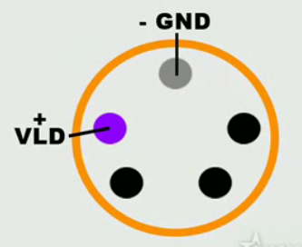 Here is the still that you'll find in the video I reference about making a "Laser phaser." It shows the two most important terminals, ground and positive for the blue laser.
If you use this image as a reference, you can see that it matches with the fuller description of the component, which includes pins for the red laser and infra-red laser diodes that are integral to the part. Here is that pinout:
- Pin 1: (Bottom Left-Hand corner) - Infra-Red Laser +
- Pin 2: (Left and Center) - Blue Laser +
- Pin 3: (Top Center) - GROUND -
- Pin 4: (Right and Center) - Red Laser +
- Pin 5: (Bottom Right-Hand corner) - Photo diode (used for power regulation when connected)
(Lay the diode on a flat surface in front of you, with the diode's pins facing you. The perimeter of the diode is round, but it has a flat edge. Roll it so that the diode's flat edge meets the flat surface and lays still. Now you're looking at the five pins like a pentagram, with one in the middle at the top. Number the pins 1-5, starting with the bottom left corner and moving around the pins clockwise.)
Finally, keep in mind that the diode component's can is itself grounded (you should verify this yourself by continuity with your meter), and can be easier to solder to than the tiny gold pins on the back of the diode.
Working Power Settings
The final circuit consisted of matched NPN transistors with their bases connected together and emitters tied to ground. On the reference side, there was a 560 ohm resistor between the positive terminal of a 9V battery and the base and collector of one transistor. Four other resistors, valued 470, 1k, 2.2k, and 4.7k ohms were in parallel with switches so that each one could be added parallel with the reference resistor. This allowed for a linearly variable equivalent resistance from 180 to 560 ohms.
The diode was in series with a 47 ohm resistor between the positive battery terminal and the collector of the second transistor.Honestly, Eric is awesome, but we just cobbled this thing together. It's probably better if you hit Sam's and get a known good circuit for your project. Your results are not guaranteed, ect.
Diode Component Notes
I used jeweler's screwdrivers for some of the extraction, and when I got the thing down to the diode itself and the armature that held it, I had to extract solder from a ribbon cable to free the component from the remaining bit of board before I could work on popping the can free of its bracket.
Your own technique is as likely to work as well as mine, but whatever you do, don't damage that diode can or the pins or the lens!
Anytime the diode is around other electronics, it should rest grounded. We soldered a ground wire to the can rim and used that as our master ground.
 If you set the diode in a new collimator, finger-tight pressing (or hot gluing, or both,) will not do. The can must be fully seated in the recess for the diode to sink heat away via the metal contact of the collimator housing. I gently locked the housing in a desk vise and pressed in the diode by the rim edges with needle nose pliers until it popped into place.
I then soldered the rim/collimator interface for better metal-to-metal contact and put on a grounding wire.
Hope this helps! I'll try to answer questions in the comments.
No comments:
Post a Comment