Monday, February 24, 2014

PS3 Laser Diode Specs

Recently I brought my posts about building a blue laser pointer (from 2008) back to life on this blog.

PS3s were brand-new tech when I wrote those, but now they're a generation or two (or maybe three) old, and you might have landed here wondering what you can do with the junk you have that used to be a really cool gaming system.

I should have a central place for the technical specifications of the PS3 laser part itself, and the arrangement that worked for us, in a concise text.

Here I'll collate from the four build posts;

  • Diode Pinout
  • Working power settings
  • Brief description of diode component extracting, installing, handling
  • (!!) Full power supply circuits will not be provided here. Sam's Laser FAQ is my usual recommendation for anything laser-related. Better yet, design your own. Make friends with someone smarter than you. All good strategies.

Here we go.

Diode Pinout


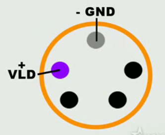
Here is the still that you'll find in the video I reference about making a "Laser phaser." It shows the two most important terminals, ground and positive for the blue laser.

If you use this image as a reference, you can see that it matches with the fuller description of the component, which includes pins for the red laser and infra-red laser diodes that are integral to the part. Here is that pinout:

  • Pin 1: (Bottom Left-Hand corner) - Infra-Red Laser +
  • Pin 2: (Left and Center) - Blue Laser +
  • Pin 3: (Top Center) - GROUND -
  • Pin 4: (Right and Center) - Red Laser +
  • Pin 5: (Bottom Right-Hand corner) - Photo diode (used for power regulation when connected)

(Lay the diode on a flat surface in front of you, with the diode's pins facing you. The perimeter of the diode is round, but it has a flat edge. Roll it so that the diode's flat edge meets the flat surface and lays still. Now you're looking at the five pins like a pentagram, with one in the middle at the top. Number the pins 1-5, starting with the bottom left corner and moving around the pins clockwise.)

Finally, keep in mind that the diode component's can is itself grounded (you should verify this yourself by continuity with your meter), and can be easier to solder to than the tiny gold pins on the back of the diode.

Working Power Settings


Close to it, rather. Assume we're using a fresh 9V battery. Following is my friend Eric's description of the power setup:
The final circuit consisted of matched NPN transistors with their bases connected together and emitters tied to ground. On the reference side, there was a 560 ohm resistor between the positive terminal of a 9V battery and the base and collector of one transistor. Four other resistors, valued 470, 1k, 2.2k, and 4.7k ohms were in parallel with switches so that each one could be added parallel with the reference resistor. This allowed for a linearly variable equivalent resistance from 180 to 560 ohms. 
The diode was in series with a 47 ohm resistor between the positive battery terminal and the collector of the second transistor.
Honestly, Eric is awesome, but we just cobbled this thing together. It's probably better if you hit Sam's and get a known good circuit for your project. Your results are not guaranteed, ect.

Diode Component Notes


If your diode arrives and is still part of a laser lens assembly from a disc drive, then you'll need to very carefully extract that diode.

I used jeweler's screwdrivers for some of the extraction, and when I got the thing down to the diode itself and the armature that held it, I had to extract solder from a ribbon cable to free the component from the remaining bit of board before I could work on popping the can free of its bracket.

Your own technique is as likely to work as well as mine, but whatever you do, don't damage that diode can or the pins or the lens!

Anytime the diode is around other electronics, it should rest grounded. We soldered a ground wire to the can rim and used that as our master ground.

If you set the diode in a new collimator, finger-tight pressing (or hot gluing, or both,) will not do. The can must be fully seated in the recess for the diode to sink heat away via the metal contact of the collimator housing. I gently locked the housing in a desk vise and pressed in the diode by the rim edges with needle nose pliers until it popped into place.

I then soldered the rim/collimator interface for better metal-to-metal contact and put on a grounding wire.

Hope this helps! I'll try to answer questions in the comments.

Sunday, February 23, 2014

Violet Blue Laser Pointer Build Part 4

Violet Blue Laser Pointer Build Part 4


Finished Product:

At last, we have a handheld, easily portable, blue/violet laser pointer. It runs on a single nine volt battery, has tunable output, a momentary switch for easy use, an external SPST switch to keep it from lighting up your pocket, an internal master power switch to make extra sure, and it's all in a very attractive black metal case!

Tuning the collimator was both easier and harder than expected. To dial it in, you simply move the threaded lens assembly around until you get the finest dot the optics will allow. Sadly, it's not the best collimator, and beam divergence is quite obvious at a range of fifty feet or so. Better collimation would do wonders for this unit, and might even yield enough light concentration power to pop balloons and light matches.

The blue beam is clearly visible in the night sky, and pointing to stars is easy and fun with this laser. Even with the beam convergence issue, the dot is remarkably bright at several hundred feet, which is plenty far to point out stars, tease animals, and play with at concerts.

When I light it up in public places, it's fun to watch people look around for the source. If the area is dim at all, then the visible beam points right to me, so keeping it on continually is a dead giveaway. In daylight, its source is much harder to find, but it's also a little less noticeable in the first place, with ambient light washing the dot out a little. Green lasers are excellent for this sort of fun as well.

Second Thoughts:

Obviously, I'd like to have been more cautious with our first Blu-Ray laser diode. Doing it right the first time would have saved us at least two weeks and $50. Still, this was a relatively inexpensive project, and if I hadn't been comfortable with the time and monetary investments, I wouldn't have chased it in the first place. If you take my experience in counsel and preserve your own diode because if it, so much the better.

These blue lasers are really, strikingly bright. I feel constrained to warn again that eye safety precautions are a must. Eric and I were careful never to power the laser unexpectedly, and to always indicate to one another where it would be pointed. When even the reflection of the dot on the wall seemed unreasonable to look at, we didn't. We could have been more careful by wearing laser-specific eye protection, and perhaps we should have, but we didn't want to spend more money on goggles that we might never use again. It probably goes without saying; if you build one of these, keep it away from kids and others with poor impulse control.

Eric and I missed out on a big opportunity to make this thing cooler than we had at first imagined. A few days after our Blu-Ray laser project was complete, I was cruising Ebay to see what kinds of blue laser items were available there. I found a seller who apparently orders in PS3 Laser Lens Assemblies, extracts the diode, and then sells the diodes on Ebay as his own product. The photo in his auction exactly matched the appearance of my diodes still in their metal mounts from the PS3 lens assembly, and I was curious. When I emailed him asking if it was a diode from a PS3 Laser Lens Assembly, I must have hit a nerve, because he never answered. I did find his website through his auction page though, and here it is, Indigo Lasers (Defunct Link removed. -Ed).

I'm not linking to Indigo Lasers to shame him in any way. I think that it's great to see the entrepreneurial spirit in action, though he could be a little more forthcoming about his parts sourcing. I'm linking because he's created some interesting technical schematics of the laser diodes. This page in particular (also dead link -Ed) piqued my interest, because it shows the pin outs for all of the lasers in that part; Blue, Red, and Infra-Red!

Had Eric and I realized that our diode was capable of emitting three laser colors, we surely would have incorporated more than one into our circuit, and given at least the red one a switch. As it stands, we can go back and rework it, but it may be wisest to leave this one as is and start a new one for a more integrated laser experience. We can make a better go of it the second time, and then we'll have two!

I would like to post a snippet of Indigo Laser's pin out map, and doing so would surely be within fair use guidelines, but the fellow running that site seems secretive enough and already worried about his documents being stolen. (He's overlaid a clear photo over the real one on the site to discourage people taking a copy. Didn't stop me, shouldn't stop you.)

Instead of posting part of his schematic and sending him into Red Alert mode, I'll simply describe the pin out here. Lay the diode on a flat surface in front of you, with the diode's pins facing you. The perimeter of the diode is round, but it has a flat edge. Roll it so that the diode's flat edge meets the flat surface and lays still. Now you're looking at the five pins like a pentagram, with one in the middle at the top. Number the pins 1-5, starting with the bottom left corner and moving around the pins clockwise.

Pin 1: (Bottom Left-Hand corner) - Infra-Red Laser +
Pin 2: (Left and Center) - Blue Laser +
Pin 3: (Top Center) - GROUND -
Pin 4: (Right and Center) - Red Laser +
Pin 5: (Bottom Right-Hand corner) - Photo diode (used for power regulation when connected)

Final Thoughts:

This was a really fun project. I've known Eric for something like fifteen years now, and I was actually glad that I wouldn't be able to get it done on my own. When we finished the project, we took our wives to a nice dinner. We've both got great wives. (Hi honey!)

Speaking of wives, Crystal was reading through one of my drafts of this write up, and she said that it seemed that not many people would be able to pull this project off. I really have to disagree with her there.

For one thing, Eric and I really made it harder than it had to be, both by designing our own circuit, and also by letting things get out of hand with our first diode. Sam's Laser FAQ is the definitive online resource for all things laser related, and Sam's even got pre-designed circuits you can build straight from given specs there. (There's also a special section at Sam's that's all about Blu-Ray diodes that I seem to have missed when I was researching. Or maybe it's new?) And as for the power snafu, Eric and I really knew better. We even joked while we were doing it that it wouldn't be a surprise if we fried the diode. Sure enough, we did.

If you're thinking about building your own blue laser pointer, I would suggest the following:
  • Know how to solder. This isn't a hard project where soldering is concerned, but you should at least know how first.
  • Don't worry about making yours look like mine, or anyone else's. Focus on the parts and objects around you that could be a case, or a switch, or whatever.
  • Find a friend who's interested and have fun with it. Hopefully, your friend will be able to help out when your skills aren't quite where they could be.
  • Take your time. No need to get sloppy and ruin your hardware.
  • Follow the tips above about not burning out your diode.
  • Don't forget that your safety is paramount. Don't be careless.
Last of all, have fun with this great project.

Thursday, February 20, 2014

Violet Blue Laser Pointer Build Part 3

Violet Blue Laser Pointer Build Part 3


Tragedy Strikes:

We left work on the case for a while to experiment with more power settings for the laser diode.

Rather than stringing you along for a cliffhanger payoff, I'm going to tell you now; we killed our first blue laser diode. The poor thing never had a chance.

Here's what happened. We had already found our lasing range, but we wanted to get the laser really pumping out the light. In the Laser Phaser video, he's got the blue beam clearly visible in the air, in a lit room. When we first got our unit to lase, it put a dot on the wall, but the beam was not visible, even in the dark. So we began ramping the power to see where the sweet spot would be.

We did this experimentation with only the light of my work desk lamp, so that changes in beam visibility would be obvious in the dim room. As we decreased the resistance in the circuit, we found that the laser had a stepping tendency; its output would make sudden, marked increases at what seemed to be consistent power thresholds. Simply tuning the potentiometer up and down made no visible difference, unless the tuning crossed a power threshold, at which the laser's output would suddenly jump, even when we accounted for the logarithmic curve of the potentiometer's range (which made the potentiometer truly effective only in the top 1/5 of its range).

The laser's stepping behavior fascinated us, and it made us eager to see what higher and higher steps would yield. Soon we were seeing not only the beam in the air, but a more and more pronounced beam, and a blue/violet dot on the wall that was so bright that we dared not look at it. These were impressive results, but like Icarus, we didn't know our limits and ended up getting our wings burnt off.

We had become accustomed to being able to predict the step ranges. In our setup, each step seemed to cover 40 Ohms of resistance or so. But now the laser's apparent brightness wasn't changing at the predicted stepping levels. Very soon we found that it wasn't lasing at its former brightness even at higher power settings than previous, and it became obvious that it was damaged. It still lit, but it did little to nothing at our former normal power levels, and it needed more and more power just to keep it lasing within one range of brightness.

During this session, the diode can became notably warm. This is testimony to the fact that even if we had kept it in a reasonable power range, we should have had better thermal management in place. It's possible that if we had done so, that first diode would be happily lasing away today.

Far more quickly than we had expected possible, we had reduced a fine blue laser diode to a very lovely and expensive violet LED. Here are my two tips for not killing your Blu-Ray laser diode. They're very simple, but surprisingly easy to violate:
  1. Mount your diode properly in a metal chassis that will sink heat away from it. Blue lasers are new tech, and they're still quite sensitive. Red, IR, and Green lasers I've worked with have seemed far less delicate to me where thermal dissipation is concerned.
  2. Find a power setting that causes your diode to lase at an acceptable level and use that setting. Ramping the power ever upward to see just how bright a beam you can get is fun, but ends with a dead laser.
That's it. Give your laser an elegant, efficient way to manage (waste) heat, and don't overfeed it.

Eric and I called it a night, and the next day I ordered another PS3 Laser Lens Assembly.

Project Execution, Take 2:

Two weeks later the second PS3 laser assembly arrived, again from Monaco. (What on earth are they doing in Monaco in the first place? Wouldn't China or Taiwan or Hong Kong or Los Angeles make a lot more sense?)

Once I had the new laser diode extracted from its lens assembly, I was determined to seat it correctly in the collimator housing. This is difficult to do, as A.) the diode can is made of thin, crush-able metal, B.) the diode pins are on the side that needs to be pressed from, C.) the back end of the diode has precious little surface area to press on, let alone avoiding the pins, and D.) the whole thing is small, fiddly, and difficult to tool up for properly without purpose-built equipment.

I ended up putting the collimator collar very gingerly (didn't want to crush it) into the desk vise, and using the tips of needle nosed pliers to press down on the disc of the rear end of the diode. I was very relieved when it popped into place.

I figured that soldering the interface ring between the diode housing and collimator would improve heat dissipation through the collimator so much the better, and I realized just in time that the diode's ground pin is in fact grounded to its housing can, so I went ahead and soldered the ground wire along with the ring of solder at the same time. This way, I'd have to only solder one of the delicate little pins on the diode itself.

I now had the two benefits with the new diode that I had forgone with the former; the diode was fully seated and soldered in for improved heat dissipation, and it was properly aligned with the lens in the collimator to maximize light use.

Now that we were truly up and running again, Eric got back to work on the power circuit. After the debacle of losing our first laser diode to carelessness, we decided that overkill for the sake of safety in the power circuit was warranted. Eric's new power supply would be transistor regulated.

There was more work to be done on the case. I still hadn't installed the hard power switch (SPST) yet, and I still needed to template, cut, deburr, and drill holes for the screws in the case. The process is fairly straightforward, so I'm not going to burden this post with too many more photos.

Power Details:

The idea all along had been to install a potentiometer in the case so that the laser's intensity could be tuned up and down. The added benefit to this idea is that when a fresh battery is installed, or the battery is getting weak, the potentiometer can make up the difference in either direction, leaving the laser operating in its 'normal' power range.

An issue we had encountered before burning out our first laser diode and up to this point, is the logarithmic curve exhibited by potentiometers in this kind of circuit. We would install a potentiometer of the proper value and give it power, and we'd only get any real ranging from tuning the potentiometer in the top or bottom 20% of its range. For all the knob turning and sudden effects, it might as well have been a switch.

In addition to that issue, I had a depressingly meager supply of potentiometers on hand. None of these had any obvious and easy method to mount them to the case. One had evenly spaced through-hole pins that we could mount on a circuit board and then attempt to line the board up with a purpose-made hole in the case, but the whole thing just felt too shaky.

After a couple of early iterations of Eric's regulated power circuit, we decided to build in a resistor network instead. A switched resistor network would allow us to put resistors of known value in each of the slots from low to high, and then the resistance could be tuned up and down coarsely and finely, depending on which parts of the network were switched on or off. A five station dip switch block I harvested from an old motherboard would do the trick nicely. (Dip switch number five, colored red in the photo below, is one of the device's three power switches.)

As I said before, I'm not all that strong in electronic theory, so here's Eric's simplified explanation of the power supply we ended up building:
The critical parameter in a driver circuit for an LED is the current. Most circuits provide a voltage, which is not desirable in this case. Therefore, we investigated current mirroring circuits using paired transistors. 
One promising avenue was a Widlar current mirror, which would scale the reference current to provide the load current. It is desirable in this case to have the load current be a multiple (possibly a large multiple) of the reference current since that would reduce the total power consumed in the circuit while allowing us to have a wide, linear dynamic range on a voltage divider that used a 20k potentiometer. 
Unfortunately, the Widlar circuit didn't perform properly and proved to be unusable. 
We ended up with a very straightforward current mirroring circuit. The circuit still passed more current through the diode than through the reference load, but the difference was smaller and more predictable than with the Widlar mirror. 
One problem with the circuit was that the load current would slowly ramp up as the diode (or the transistors?) would heat up. We didn't investigate that effect in any detail. 
The final circuit consisted of matched NPN transistors with their bases connected together and emitters tied to ground. On the reference side, there was a 560 ohm resistor between the positive terminal of a 9V battery and the base and collector of one transistor. Four other resistors, valued 470, 1k, 2.2k, and 4.7k ohms were in parallel with switches so that each one could be added parallel with the reference resistor. This allowed for a linearly variable equivalent resistance from 180 to 560 ohms. 
The diode was in series with a 47 ohm resistor between the positive battery terminal and the collector of the second transistor. 
There is nothing magical about any of these values. They were arrived at experimentally, except for the parallel network resistances which follow a geometric sequence in order to allow the equivalent resistance to vary linearly. 
At least the current mirror circuit helped us reduce the likelihood of burning out the diode.
Thanks Eric!

Next came the soldering, which would be my job. I foolishly didn't have any flux on hand at the time, making the job much more difficult than it had to be.

An issue I had with the soldering was that after we laid all the components on the board, I had to find a way to turn the board upside-down for soldering without all the components falling out. For this, I simply wadded up a face tissue and taped it to the top side of the components. The fluffy nature of the tissue pressed against the components kept them all pressed into place, despite their differing sizes and positions.

Eric created a spreadsheet with a diagram of which wires connected where, and connection by connection, I got the soldering done. When we tested the circuit after soldering, it didn't work at all. Eric carefully checked my work, and found that I had missed one of the ground connections. A quick revisit to the underside of the board with the iron had everything up and running.

Testing confirmed that our wiring was right and our resistor network was functional as designed. I then used the Dremel to cut the circuit board in half, leaving the other half for future projects and saving space in the case of the current one.

We didn't want vibrations wearing on the four soldered wires leading to the board (two for power in from battery, two for power out to diode), so I hot glued everything down. I also glued over all of the exposed solder connections on the bottom of the board so that they'd be well insulated from the surrounding metal case.

Once we had everything wired up and tested, I soldered all of the twisted wire connections and taped them for electrical insulation.

Next was the fun process of hot gluing everything in place, except for the laser collimator and the battery. They both should be movable.

This was also a good time for final tuning of the collimator lens, which simply has threads on the outside of its plastic housing that match threads on the inside of the collimator collar and a spring between them to keep it all under tension.

Finally, I cut up the foam blocks that came in the pen case and hot glued them into positions to hold the battery and collimator in place in the case. This keeps everything quiet and sturdy, but allows for removal and tweaking of each.

Conclusion and Wrap-up will be posted tomorrow!

Wednesday, February 19, 2014

Violet Blue Laser Pointer Build Part 2

Violet Blue Laser Pointer Build Part 2


Oh, one more thing:

Your visual safety is the most important factor to consider when undertaking a project of this kind. Please be cautious around lasers, and never allow a laser beam the remotest possibility of passing near or into an eye. I strongly recommend reading the "Laser Safety" portion of Sam's Laser FAQ. Also, parts of this project involved cutting and grinding metal, both of which create flying metal shards. Eye protection when operating cutting and griding equipment is an absolute imperative. 

Further, the post, posts, documents, text, photos, and any other media that are part of this series documents only my own project, and should not be regarded as advice to you. You undertake any project completely at your own risk. 

That said, here we go.


Project Execution, Take 1:

The PS3 Laser Lens assembly shipped from Monaco, of all places. It took far longer to arrive than I had anticipated, and the company I ordered it from was unresponsive to my requests for updates. I was literally one day from filing a charge back on it with my credit card company when it arrived.

The nondescript white box had me a little nervous at first. How could I know that I actually had a Blu-Ray component here? I would just have to carry on and find out when I power it up. But I couldn't power it up until I had it disassembled.

The lens assembly cover came off easily, and it was neat to see all of the laser lenses arrayed inside. Some of them were mounted on coils that could be moved around with small magnetic braces around them (coincidentally, this is also how the armature in your hard drive moves the read/write heads around on the platters).

The laser diode can be seen on the far left side of this photo, sitting horizontally with its soldered metal brace being the two metal points at the far left of the assembly. The laser is aimed through an initial lens block, and then through a splitter block, where the beam is apparently divided, perhaps by wavelength frequency (beam color).

The sheer number of lenses in this assembly impressed me. I've harvested laser diodes from CD burners and DVD drives, and they usually have very simple lensing compared to this. I suspect that blue lasers being a relatively new technology, the diodes aren't yet advanced enough to give quite the right beam properties straight from the component, and the beam needs a lot of work before it's ready for use in reading media. Thus, the extensive lensing.

It seemed to me that all of those cool lenses might be useful at some point, so when I got the diode free of the assembly chassis, I set the rest aside for more work at some future date.

This is a shot of the laser in its chassis, removed from the main lens assembly. The through hole ribbon cable connector was removed by locking a corner of the diode chassis into the desk vise, and then using copper solder wick to remove the solder and get the pins free so that the connector could slide off of them.

Below is a simple current limiting circuit we built to test things out with. We decided to start with high values of resistance and slowly ramp down to find where the diode would begin to light, and then lase. Once we had our ballpark, we would put a potentiometer on the circuit to help with fine tuning.

This was an early test circuit. I don't know resistor color bars on sight, but it doesn't really matter, because this one got the laser diode to glow like a dim LED, but it was nowhere near lasing. At any rate, it's good to see some of the breadboarding and testing process. You can add up the resistor values for yourself if you like.

This next photo is important to me, because it illustrates our first big mistake. What you'll see here is the laser diode, now removed from its metal housing, and put into the collimator sleeve (also metal, but thick and round). The original red laser was press-fit into the collimator sleeve. It was so snug in the sleeve that pressing it back out damaged the red laser diode can. I was loathe to damage the blue laser diode can by trying to fully press it into the sleeve, so instead I got it in as snug and straight as I could with my thumbnail and then hot glued it down.

Failing to press-fit the diode into the collimator sleeve was a mistake because the diode is intended to use the surrounding metal housing to sink heat away from itself. Without this precious thermal management, the diode is likely to fail even under normal operating power.

Further, the groove in which the diode is seated when it is press-fit is designed to align the diode can so that the beam travels into the collimator lens at as close to the ideal 90 degrees as possible. Simply placing it on the groove, or only pressing it in partway leaves the diode can both misaligned and physically further from the collimator lens than intended, leading to inefficient use of the light source and making beam tuning as intended impossible.

Our first powered tests produced only a dim LED glow from the diode, but as we ramped up power by decreasing resistance in our test circuit, we quickly brought the diode from a dim glow, to a bright glow, to dim lasing, to bright lasing.

We were so excited to see lasing that we turned off the lights in the room and took photos of the blue laser on a wall, but it's a classic "you had to be there" moment; the photos themselves are unspectacular. I won't post photos of a black background with a bright blue dot here for the sake of your sanity.

By this point, Eric had a good idea of the power range needed for the driver circuit, and he grew quiet as he thought about different design options. I left him to it and began work on the case for the laser.

So it's a black metal pen case. I pulled out the foam inserts and stared at it for a while to try to conceptualize the best way of mounting the laser guts inside. Once I felt I had an idea, I took the parts I had at hand and put them into the case to see if they'd fit as visualized. I didn't have a power circuit yet, so I arranged everything, leaving a big gap in the middle and asked Eric if he could commit to his circuit fitting there. He felt that the space provided would be ample, so I got to work on the cutting and drilling that the case would require.

You can see the dot I made on the case with a silver sharpie. To determine the right location for the hole, I simply popped in the collimator and lined it up with the natural front curve of the case. Where the lens ended up is where I needed my hole. I started the hole with a 1/16" drill bit, and then used an Irwin Unibit to step the hole up to 5/16" or so. I then used a Dremel grinding stone to deburr the hole.

Ergonomics are a factor with a laser pointer, so the momentary switch was next. Toward the front of the unit, next to the laser aperture seemed to make sense, so I made an outline for cutting to place the switch. The switch handily came with a collar (which, in a rare moment of brilliance, I had been smart enough to save), so all I needed to install it was the right sized square hole.

I traced the smaller, inner collar size onto the outside of the case with the sharpie and used that as my cutting template. I didn't worry too much about keeping it neat, as the larger, upper collar would cover any small sharpie fudges I made.

Dremel Note 1: Here I'll note that if you don't have a Dremel in your shop, you should really prioritize getting a good one for regular use.

My first "rotary tool" was a Black & Decker Dremel knock off, which I thought would be a good investment rather than a real Dremel because it took a VersaPak battery, along with several other tools I had at the time. Boy, did Black & Decker teach me a lesson. Dust Buster, yes. All other tools, no. They were right to kill off the VersaPak line, but it's too bad that I was suckered into buying any of that garbage in the first place.

Lesson learned. I buy quality tools now. My drills (well, one is an electric screwdriver) are DeWalts, and my Dremels are really Dremels.

Dremel Note 2: If you plan to do any kind of material cutting with Dremel's pressed sand cutting discs, make sure you keep a lot of the discs on hand. They shatter before they flex, and the shattering is just as soon induced by looking at them funny while in use as smashing them with a hammer. This makes eye protection doubly important, as cutting wheel chunks are relatively large, sharp and heavy, and the rotational speed launching them yields incredible velocity in flight. Goggles stop them easily enough, but you don't want your corneas doing that job for sure.

Part 3 Tomorrow!

Tuesday, February 18, 2014

Violet Blue Laser Pointer Build Part 1

(Editor's Note: This appeared on an Entrepreneurship Website that I used to own. It's been at least six years since Eric and I built this (it was posted in 2008), and we remain in touch, and this remains a treasured experience. Since the old entrepreneurship blog no longer exists, I'm posting this technical and fun, but very very long build log here at Phischkneght Extended. Probably with some very light editing. Also, since this post is huge, I'll post it here as three or four parts. Hopefully there are more to come. Cheers. Feb. 2014)

The end of the Blu-Ray/HD-DVD format war (Blu-Ray won, if you haven't been following along) signals the beginning of two changes:
  1. For a very limited time, HD-DVD players will be available at prices far below commodity value. Dead, unsupported tech never fares well in the mass marketplace.
  2. Over the long term, Blu-Ray hardware will follow the natural downward price curve that all consumer commodity tech shows over its life.


When Crystal and I got married in 1999, she wouldn't let me add a DVD player to our gift registry because she couldn't imagine anyone buying us a $500 video player. Today if you watch retail spaces carefully, you can buy a cheap DVD player for $20 or so. It seems extraordinary, but for a tech item, it's a perfectly typical curve. (For a much more radical example, compare 1999's 500MB hard drive for $150 to today's (2008)1TB hard drive for $200. That's 2,000 times the storage space for $50 more, less than ten years later.)
The practical upshot of the two points above is that from here on out, blue lasers are increasingly in the realm of economical hacking projects.

Practicality/Conception:


I make it my general policy not to get involved in the annual Black Friday madness. Once in a while I make an exception, like when I managed to buy The Orange Box at Best Buy for $25 last year (the cake is a lie, Mr. Freeman). 2007's pre-Black Friday hoopla included a press release from Wal-Mart that they'd be offering limited stock of a certain model of HD-DVD player for under $100. I was itching for a project at the time, and my green laser seemed to be getting a bit long in the tooth, so I decided to look into creating a blue laser pointer with an HD-DVD laser diode

The response of my fellow Mefites to the laser question was mediocre, but it did yield a link to this video, which, strangely enough, had been posted the same day I asked my question. It's a very cheesy video, and the creator of the laser pointer in it shows gross disregard for both his own safety and for the health of his laser diode. But the video did serve as an extremely useful idea seeder:

    1. It confirmed to me that a blue laser diode could be harvested and used in a project.
    2. It showed that the diode could be driven by a nine volt battery.
    3. It showed that at its core, the project could involve a very simple power circuit (though the nice tuning regulated circuit we ended up with is much more complex).
    4. It illustrated a source for the laser diode component that I had not (but should have) thought of.
    5. It provided a pin out for the blue laser portion of the laser diode.
    6. I was worried about beam collimation, and this video answered that concern very nicely, with a collimator hacked off of a separately purchased red laser.
    I've criticized the video more than once now, and I should explain why:
    1. The phaser casing isn't as portable as I wanted my final product to be. Oh, and it's tacky. I like Star Trek, but that's just not slick enough for me. 
    2. The video talks about extracting the diode from the laser lens assembly, but does not illustrate how this was done. I found that it's not terribly difficult, but it is a rather delicate process at the point where the diode needs to be extracted from its own little mounting chassis.
    3. The video didn't provide the pin out for the non-blue laser contacts on the diode (more on this later).
    4. The video does not show how the laser diode is secured to the front portion of the collimator assembly. From the video, it looks as if it was done with hot glue, which would negate much of the heat sinking abilities of the collimator assembly, leading to the diode overheating and burning out.
    5. The guy in the video uses one resistor in serial with the nine volt battery to the diode, never mentioning the value of the resistor or why he used that value.
    6. Getting the collimator off of the sacrificial red laser was non-trivial, and it nearly ruined the red laser diode. Not such a big deal, but a mention would have been nice.
    7. The video dialog did not point out that the laser was likely running in the top of its power range, meaning that it would be very sensitive to overheating even with proper heat sinking. My guess is that if his "laser phaser" has had much use at all, the laser diode is in the late stages of progressively burning out by now.
    8. He makes no mention of eye safety where lasers are involved.

    As mentioned in the above list, I realized that buying an entire HD-DVD box would be entirely unnecessary for sourcing a blue laser diode. Those active in the game console modding scene know that parts can be sourced for replacement for just about any current gaming system, including the PlayStation 3 (which of course, uses a Blu-Ray laser as its primary media reader). It seemed like such a no brainer, and I should have thought of it on my own. After heading on over to a couple of my favorite online console parts dealers, I found the PS3 laser lens assembly that I would end up buying.

    Now that I knew that I could source the critical blue laser diode component, I began to get excited. I'd been seeing Sonar Blu-Ray pointers, walkthroughs on building your own (non-blue) laser pointers (Used to have a ref link to Magus Lasers here, but the site is dead and Google offers no replacement -Ed Feb2014), the ThinkGeek blue laser pointers, and even Wicked Lasers, (where, even today at this writing, you can buy the above Sonar Blu-Ray pointer for a ridiculous $2,000) for months by this time.

    Now it was starting to look like my turn.

    But first, I needed to make sure that I could pull off this project. Crystal was unlikely to let me spend $50-$70 on a blue laser diode if the odds weren't good that I could get the project off the ground.

    Late Conceptualization, Preparation:

    I'm mostly a real-world, practical use guy. My electronics theory skills are weak, so my first call was to my good friend, Eric Widdison. Eric walked away from Utah State University a few years back with a Master's degree in Electrical Engineering. Eric isn't that good at basic math, and he can't solder worth a darn, but I knew that he would be my go-to guy for this project. (I should mention here that Eric is a terrific sport, and his advanced math skills are superlative.)

    My main concern for this project at this point was creating the driver circuit to power the laser diode. I knew that this part of the project would be critical to overall success. A bad driver circuit would fail to bring the diode to lasing state, burn it out quickly or slowly, or perhaps a combination of those. I explained the project and the need for help with the power circuit to Eric, he said that he felt confident that he could help me make it work.

    With Eric on board, I ordered the PS3 laser lens assembly and the red laser mentioned in the Laser Phaser video for the collimator. I also spent a week or so thinking about the various components I had on hand and gathering up the ones I felt might be useful to the project.


    Late Preparation, Early Execution:


    Eric and I worked out a good night for him to come over and start the project with me, and on a chilly Tuesday night, we found ourselves at my work bench with all kinds of fun hardware at hand and no idea where to start.

    We quickly decided to pick what our case would be. I had gathered several containers for the purpose, including Altoid tins, some other plastic mint cases, and a pill bottle or two. Most of the potential cases that I had chosen were determined to be too small for this project and had to be eliminated from the running.

    We settled on a metal case with a foam insert...much like a fancy pen would arrive in. In fact, it's the case my green pen laser came in when I ordered it years ago. The case was a little larger than we felt ideal, but better too big than too small in this instance.

    It was good that we settled on our case early, because we needed to begin thinking about component quantity, size, and placement right away. These were our main component criteria:
    • A laser pointer should have a momentary switch. Easy to turn on, but the default state is off.
    • It should also have a hard master switch that will ensure the laser is never accidentally powered on.
    • It would be nice to have the option of tuning output power, possibly via a potentiometer.
    • The power circuit we would build would have to fit inside the case.
    • The battery would have to fit inside the case.
    • The laser collimator housing (with the laser diode inside) would have to fit inside the case.
    With those criteria in mind, we picked through my parts collection and found a momentary switch I harvested from the packaging that a dinosaur toy came in for my son a couple of Christmases ago, an SPST (Single Pole, Single Throw) switch from an ATX power supply, a nine volt battery with a power connector, and the collimator I had already purchased for this project.

    With everything else assembled, I got out the PS3 laser lens assembly box, which had arrived that day, and prepared to begin work on it.

    (Part Two will be posted tomorrow!)